|
Get
my instant news
alerts now on Twitter!

Donate
Bitcoins

|
 PWM
PWM |
EFIE |
Cells |
Bubblers |
Solar |
Other |
|
 |
|
|
|
|
|
|
 |
The
new PWM v2.1 |
 |
|
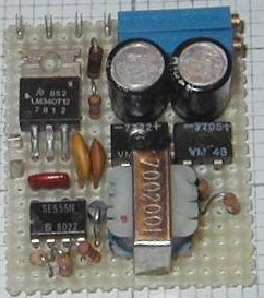
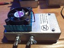 This
is a slightly modified version of my first constant current
PWM or pulse width modulator. The basic electronic circuit
is the same. Some component values have changed. And it's
layed out specifically to fit in a die cast aluminum enclosure
measuring just 4.5" L x 2.5" W x 1.25"
H. more... This
is a slightly modified version of my first constant current
PWM or pulse width modulator. The basic electronic circuit
is the same. Some component values have changed. And it's
layed out specifically to fit in a die cast aluminum enclosure
measuring just 4.5" L x 2.5" W x 1.25"
H. more... |
|
|
|
|
|
|
|
|
|
|
|
EFIE |
|
|
 I'm
still not convinced that the basic EFIE for all its virtues
is enough to fool the average automotive ECU into ignoring
the presence of HHO. It's the right idea but doesn't go
quite far enough, IMHO. I leave this info here for those
who wish to try their hand at one anyway. I certainly
hope you have better luck with one than I did. more... I'm
still not convinced that the basic EFIE for all its virtues
is enough to fool the average automotive ECU into ignoring
the presence of HHO. It's the right idea but doesn't go
quite far enough, IMHO. I leave this info here for those
who wish to try their hand at one anyway. I certainly
hope you have better luck with one than I did. more... |
|
|
|
|
|
|
|
|
RomeroUK
Muller motor replication
This topic has been moved here
|
| |
Ideas
I'm kicking around
Mathematical evidence of a mirror negative radio frequency
spectrum (Maybe even a mirror plane of existance) |
In a RF mixer circuit with F1 and F2 being injected and F1
is the higher frequency, what are the products before any
filtering at the output?
Conventional "wisdom" says you still have your two
fundamentals, F1 & F2. You also have (F1 + F2 = F3) and
(F1 - F2 = F4).
BUT, the summed output F3 is stronger than F4. Why? Because
F3 can also be expressed as (F2 + F1 = F3). Two ways mathematically
to arrive at the same output. F4 can only be expressed (F1
- F2 = F4). Amplitude is not being considered. If it were
this would be an unbalanced equation.
In my mind this really begs the question, why does conventional
wisdom discard the result of (F2 - F1)? This would account
for the missing amplitude. Just because it's a negative number
it doesn't exist? Because you don't understand it, or haven't
found a way to filter it, you throw it away? I believe there
IS a F5 and it IS a negative number. Subspace radio, here
we come! I have even drafted a way to filter it out from the
product.
If we know Fc = 1/(2*pi(sq-rt of L*C))
then -Fc = 1/(2*pi(sq-rt of -L*C)).
So how does one create negative-L? My theory yet to be explored
is a bifilar inductor connected out of phase.
AND, I believe these theories have application to the creation
of limitless HHO as well.
|
| |
Resonant cell (Yes, REALLY!) |
|
Boyce, Meyer and others were all hitting resonance by trying
to send it high frequency energy. Boyce took the shotgun
approach with a wide spread of frequencies and harmonics.
Meyer tried to zero in closer by sending it repetitive bursts
of single frequency energy and catching the resonance as
it sweeps through on each burst. They both work better than
trying to send it a single frequency and hoping to hit it.
Others are now toying with complex PLL and Micro Processors.
I have a concept on paper to track the resonant frequency
by frequency modulating a carrier signal and correcting
based on phase angle of the error signal. I almost started
down that path with my blinders securely fastened, UNTIL
I had a flash of inspiration sitting on the toilet.
You know what? We're going about this all wrong. We are
again the victims of misinformation. Either Meyer and/or
Boyce are agents of misinformation or they are victims of
it.
Think about it. The pendulum of a clock can be made to resonate
if we poke it lightly and repeatedly with our finger at
the resonant frequency. But is that how the pendulum really
operates in a clock mechanism? No. The clock spring does
not feed the pendulum pulse energy at it's precise resonant
frequency. The clock mechanism feeds the pendulum energy
WHEN THE PENDULUM ASKS FOR IT. The pendulum itself sets
the optimum frequency for itself. In electronic terms we
call this a regenerative oscillator. Even if the pendulum
weight were to shift up and down, it would still resonate.
IT'S AN OSCILLATOR!
Why are we messing with ideas on how to force the resonant
tank circuit of a cell and inductor to do something that
it WANTS to do naturally and worry about figuring out ways
to track it as the dynamics of the cell changes? Let the
tank circuit itself set the frequency. Let the tank circuit
be part of a regenerative power oscillator. Sample a portion
of the energy, amplify it and feed it back into the tank
circuit, in phase to sustain oscillation. Let it step charge
the cell until it reaches catastrophic dielectric failure
over and over. It doesn't matter how the dynamics of the
cell changes. It will constantly be at it's own natural
resonant frequency no matter what conditions change in the
cell.
THE DAMN THING IS JUST DYING TO BE AN OSCILLATOR! LET'S
SET IT FREE!!!
I'll be working on a circuit for this tomorrow, July 4th.
If it works as I think it might, this might truly become
*THE* Independence Day of all Independence Days, for all
humanity, for all eternity.
|
| |
Level sensor |
|
An idea came to me when answering a post at youtube for
a level sensor. Someone already did this by creating a probe
dipped into the elyte from the top with two bare ends to
sense conductivity when they become unsubmerged triggered
by a comparator chip. I don't know how well it worked, though.
The froth that forms at the top may be too conductive and
throw it off.
My
idea is you might be able to do it optically through the
sight tube I have on the side of the elyte tank, or the
probes inserted there where no froth collects. Just a couple
of SS straight pins pushed right through the vinyl tubing
would do it.
|
| |
|
|

